
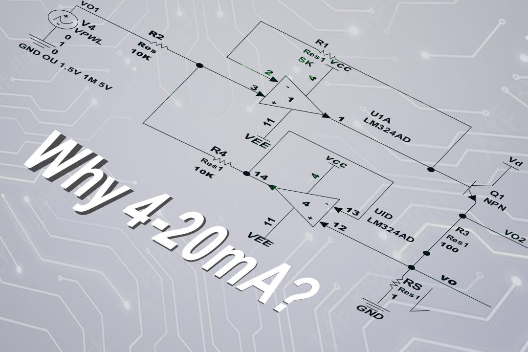
What is 4-20mA?
The 4-20mA DC (1-5V DC) signal standard is defined by the International Electrotechnical Commission (IEC) and is used for analog signals in process control systems.
In general, the signal current for instruments and meters is set to 4-20mA, with 4mA representing the minimum current and 20mA representing the maximum current.
Why is current output?
In industrial settings, using a signal amplifier to condition and transmit signals over long distances using voltage signals can lead to several issues. First, voltage signals transmitted over cables can be susceptible to noise interference. Second, the distributed resistance of the transmission lines can cause voltage drops. Third, providing power to the signal amplifier in the field can be challenging.
To address these issues and minimize the impact of noise, current is used to transmit signals because it is less sensitive to noise. The 4-20mA current loop uses 4mA to represent zero signal and 20mA to represent full-scale signal, with signals below 4mA and above 20mA used for various fault alarms.
Why do we use 4-20mA DC (1-5V DC)?
Field instruments can implement a two-wire system, where the power supply and load are connected in series with a common point, and only two wires are used for signal communication and power supply between the field transmitter and the control room instrument. Using a 4mA DC signal as the starting current provides static operating current to the transmitter, and setting the electrical zero point at 4mA DC, which does not coincide with the mechanical zero point, allows for the detection of faults such as power loss and cable breaks. Additionally, the two-wire system is suitable for using safety barriers, aiding in explosion protection.
Control room instruments use voltage-parallel signal transmission, where instruments belonging to the same control system share a common terminal, making it convenient for instrument testing, adjustment, computer interfaces, and alarm devices.
The reason for using 4-20mA DC for signal communication between field instruments and control room instruments is that the distance between the field and control room can be significant, leading to higher cable resistance. Transmitting voltage signals over long distances can result in significant errors due to the voltage drop caused by the cable resistance and the input resistance of the receiving instrument. Using a constant current source signal for remote transmission ensures that the current in the loop remains unchanged regardless of the cable length, guaranteeing transmission accuracy.
The reason for using a 1-5V DC signal for interconnection between control room instruments is to facilitate multiple instruments receiving the same signal and to aid in wiring and forming various complex control systems. If a current source is used as the interconnection signal, when multiple instruments receive the same signal simultaneously, their input resistances must be connected in series. This would exceed the load capacity of the transmitting instrument, and the signal ground potentials of the receiving instruments would be different, introducing interference and preventing centralized power supply.
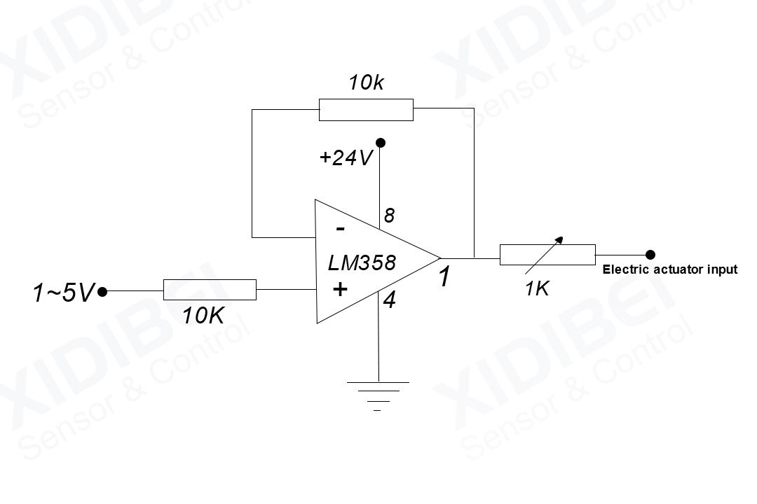
Using a voltage source signal for interconnection requires converting the current signal used for communication with field instruments into a voltage signal. The simplest method is to connect a standard 250-ohm resistor in series in the current transmission circuit, converting 4-20mA DC to 1-5V DC. Typically, this task is accomplished by a transmitter.
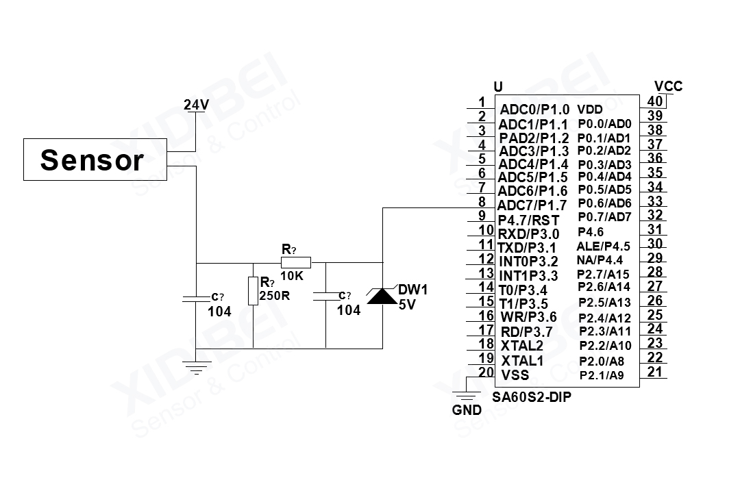
This diagram uses a 250-ohm resistor to convert the 4-20mA current signal into a 1-5V voltage signal, and then it uses an RC filter and a diode connected to the microcontroller’s AD conversion pin.
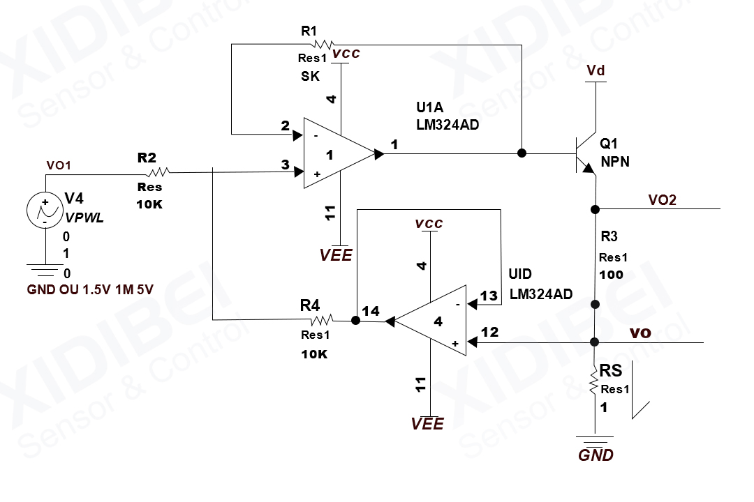
“Here attached a simple circuit diagram for converting a 4-20mA current signal into a voltage signal:
Why is the transmitter selected to use a 4-20mA DC signal for transmission?
1. Safety considerations for hazardous environments: Safety in hazardous environments, particularly for explosion-proof instruments, requires minimizing the static and dynamic power consumption necessary to keep the instrument operating. Transmitters that output a 4-20mA DC standard signal typically use a 24V DC power supply. The use of DC voltage is mainly because it eliminates the need for large capacitors and inductors and focuses on the distributed capacitance and inductance of the connecting wires between the transmitter and the control room instrument, which is much lower than the ignition current of hydrogen gas.
2. Current source transmission is preferred over voltage source: In cases where the distance between the field and control room is considerable, the use of voltage source signals for transmission can introduce significant errors due to the voltage drop caused by the cable resistance and the input resistance of the receiving instrument. Using a current source signal for remote transmission ensures that the current in the loop remains constant, regardless of cable length, thereby maintaining transmission accuracy.
3. The choice of 20mA as the maximum current: The choice of a maximum current of 20mA is based on considerations of safety, practicality, power consumption, and cost. Explosion-proof instruments can only use low voltage and low current. The 4-20mA current and 24V DC are safe for use in the presence of flammable gases. The ignition current for hydrogen gas with 24V DC is 200mA, significantly higher than 20mA. Additionally, factors such as the distance between production site instruments, load, power consumption, electronic component requirements, and power supply requirements are taken into account.
4. The choice of 4mA as the starting current: Most transmitters that output 4-20mA operate in a two-wire system, where the power supply and load are connected in series with a common point, and only two wires are used for signal communication and power supply between the field transmitter and the control room instrument. The choice of a 4mA starting current is essential for the transmitter circuit to operate. A 4mA starting current, not coinciding with the mechanical zero point, provides an “active zero point” that helps identify faults such as power loss and cable breaks.
The use of 4-20mA signals ensures minimal interference, safety, and reliability, making it the widely adopted standard in industrial applications. However, other output signal formats, such as 3.33mV/V, 2mV/V, 0-5V, and 0-10V, are also used to better handle sensor signals and support various control systems.