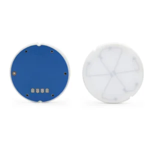
● Measuring Range: -10KPa…0KPa~40KPa…50KPa.
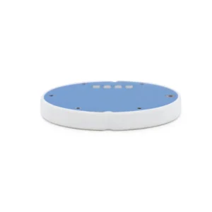
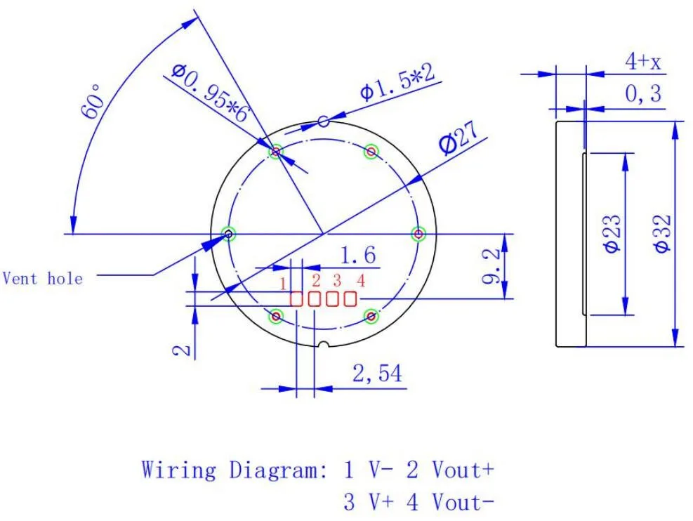
● Size: 32*(4+X)mm.
● High reliability, and flexible output options.
● Industrial process control
● Micro-pressure circumstances
● Liquid level or dust pressure measurement


| Pressure range | 0~50kpa | Size mm (diaphragm* height) | 32*(4+X) |
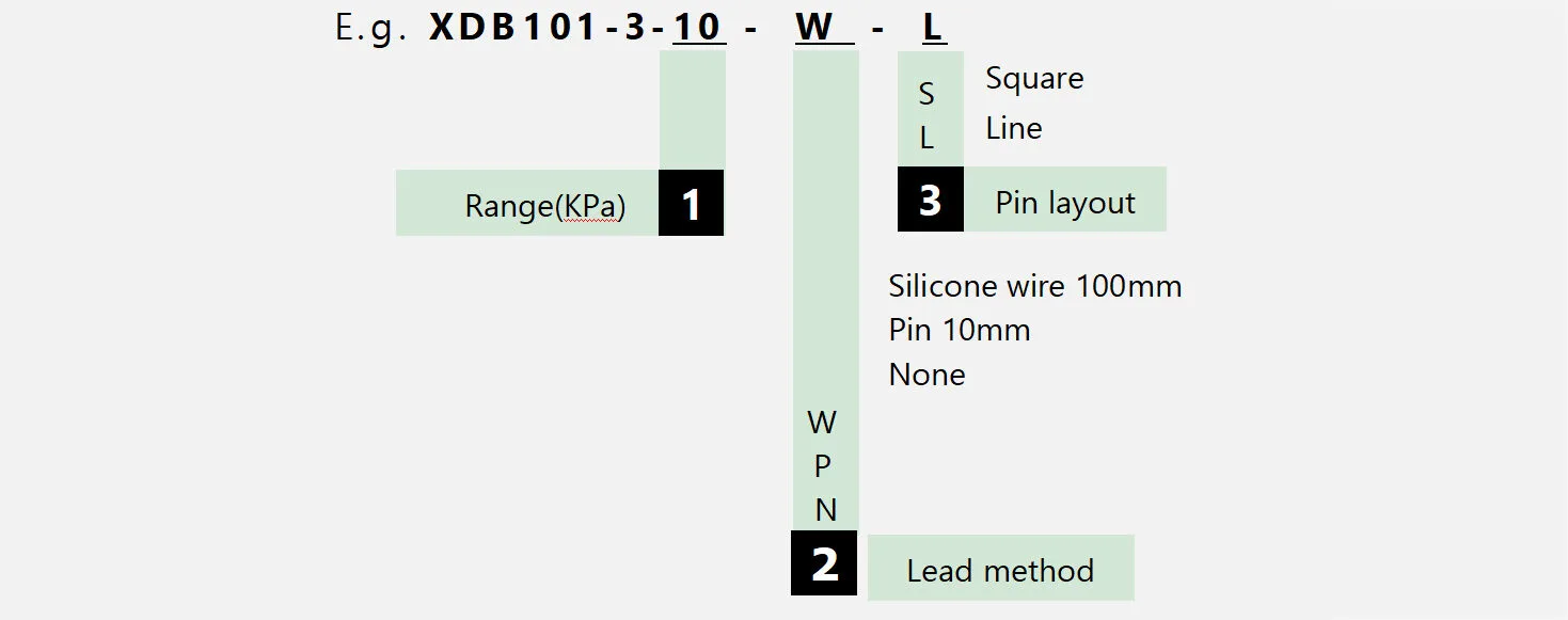
| Product model | XDB101-3 | Supply voltage | 0-30 VDC (max) |
| Bridge road impedance | Full range output | ≥2 mV/V | |
| Operating temperature | -40~+135℃ | Storage temperature | -50~+150 ℃ |
| Compensation temperature | -20~80℃ | Temperature drift (zero & sensitivity) | ≤±0.03% FS/℃ |
| Long-term stability | ≤±0.2% FS/year | Repeatability | ≤±0.2% FS |
| Zero offset | ≤±0.2 mV/V | Insulation resistance | ≥2 KV |
| Zero-point long-term stability @20°C | ±0.25% FS | Relative humidity | 0~99% |
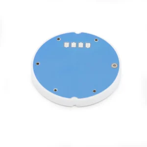
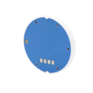
| Direct contact with liquid materials | 96% Al2O3 | Overall accuracy (linear + hysteresis) | ≤±0.3% FS |
| Burst pressure | ≥2 times range (by range) | Overload pressure | 150%FS |
| Sensor weight | 12g | ||
1. When installing the ceramic sensor core, it is important to focus on suspension installation. The structure should include a fixed pressure ring to limit the position of the sensor core and ensure even stress distribution. This helps to avoid variations in mounting stress that can result from different workers.
2. Prior to welding, perform a visual inspection of the sensor pad. If oxidation is present on the pad’s surface (turning it dark), clean the pad with an eraser before welding. Failure to do so may result in poor signal output.
3. When welding the lead wires, use a heating table with temperature control set at 140-150 degrees. The soldering iron should be controlled at approximately 400 degrees. Water-based, rinse-free flux can be used for the welding needle, while clean flux paste is recommended for the welding wire. The solder joints should be smooth and free of burrs. Minimize the contact time between the soldering iron and the pad, and avoid leaving the soldering iron on the sensor pad for more than 30 seconds.
4. After welding, if necessary, clean the residual flux between the welding points using a small brush with a mixture of 0.3 parts absolute ethanol and 0.7 parts circuit board cleaner. This step helps to prevent residual flux from generating parasitic capacitance due to moisture, which could affect the accuracy of the output signal.
5. Conduct output signal detection on the welded sensor, ensuring a stable output signal. If data jumping occurs, the sensor must be re-welded and reassembled after passing the detection.
6. Before calibrating the sensor post-assembly, it is important to subject the assembled components to stress in order to balance the assembly stress prior to signal calibration. Typically, high and low temperature cycling can be employed to expedite the equilibrium of component stress after the expansion and contraction process. This can be achieved by subjecting the components to a temperature range of -20℃ to 80-100℃ or room temperature to 80-100℃. The insulation time at the high and low temperature points should be a minimum of 4 hours to ensure optimal results. If the insulation time is too short, the effectiveness of the process will be compromised. The specific process temperature and insulation time can be determined through experimentation.
7. Avoid scratching the diaphragm to prevent potential damage to the internal circuit of the ceramic sensor core, which could result in unstable performance.
8. Exercise caution during the mounting to prevent any mechanical impacts that could potentially cause malfunctioning of the sensing core.
Please note that the above suggestions for ceramic sensor assembly are specific to our company’s processes and may not necessarily serve as standards for customer production processes.