products


XDB804 Series Thermal Gas Mass Flow Meter
Measuring principle
The thermal gas mass flow meter is designed based on the principle of heat diffusion. The instrument uses the constant temperature difference method to accurately measure the gas. It has the advantages of small size, high degree of digitization, easy installation, and accurate measurement. The sensor part consists of two reference-level platinum resistance temperature sensors. When the instrument is working, one sensor continuously measures the medium temperature T1; the other sensor self-heats to a temperature higher than the medium temperature T2. It is used to sense the flow rate of the fluid and is called a velocity sensor. The temperature ΔT=T2-T1, T2>T1. When the fluid flows through, the gas molecules collide with the sensor and take away the heat of T2, causing the temperature of T2 to drop. If ΔT is to remain unchanged, the power supply current of T2 must be increased. The faster the gas flows, the more heat is taken away. There is a fixed functional relationship between the gas flow rate and the increased heat. This is the principle of constant temperature difference.

Where ρ₉ - fluid specific gravity (related to density)
V - flow rate
K - balance coefficient
Q - heating (related to specific heat and structure)
ΔT - temperature difference
Since the sensor temperature is always automatically constant at about 30°C higher than the medium (ambient) temperature, the thermal gas flow meter does not require temperature compensation in principle.
The thermal gas mass flow meter is suitable for medium temperature range of -40-220°C.
The specific gravity and density of the fluid are related to

Where ρ₉ — medium density under working volume (kg/m3)
ρn — medium density under standard conditions (101.325 Kpa, 20℃) (kg/m3)
P — working pressure (kPa)
T — working temperature (℃)
It can be seen from the formula that the functional relationship between flow rate and working pressure, gas density and working temperature has been determined. Constant temperature differential thermal gas mass flowmeter is not only not affected by temperature, but also not affected by pressure. Thermal gas mass flowmeter is a real direct mass flowmeter, and users do not need to correct pressure and temperature.
Typical applications

Parameters

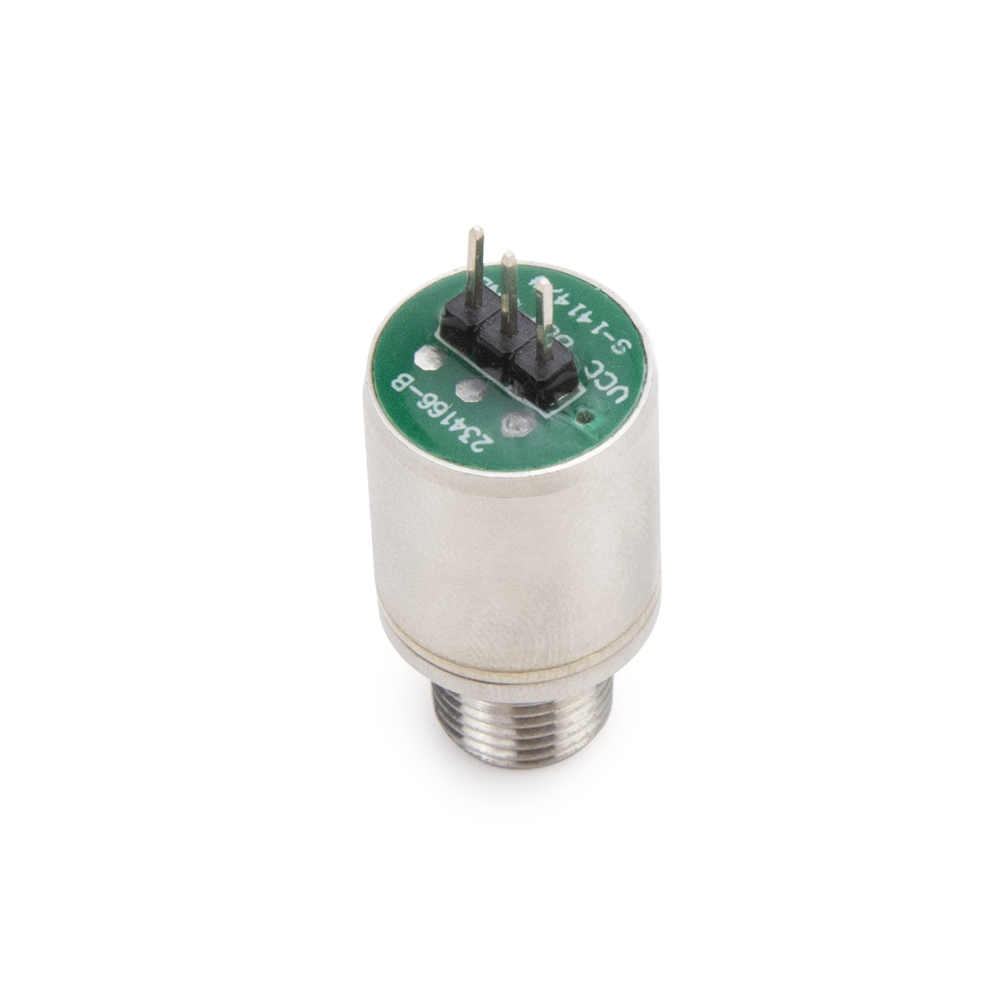
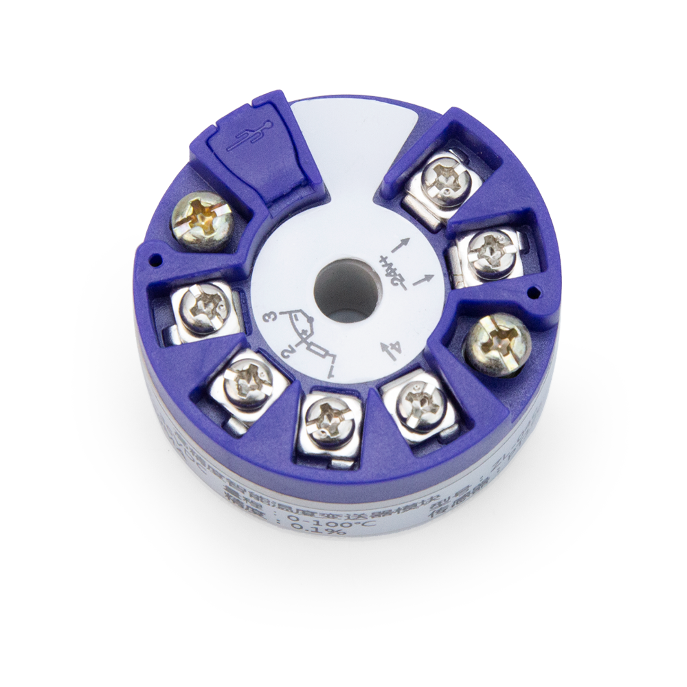
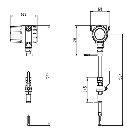
Dimensions(mm) & electrical connection
|
Terminal Block PCB Diagram |
Mark |
Meaning |
Purpose |
尺寸图 |
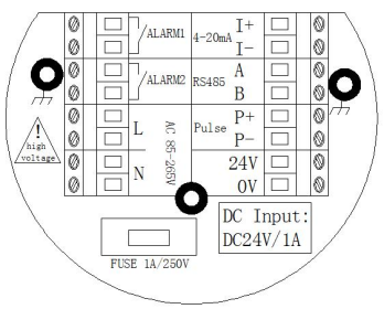 |
24V |
24V power input positive |
Instrument working voltage Description: In actual use, only one of them needs to be selected. |
 |
|
0V |
24V power input negative |
|||
|
L |
AC input live wire |
|||
|
N |
AC input neutral wire |
|||
|
P+ |
Pulse output positive |
Metering cumulative pulse |
||
|
P- |
Pulse output negative |
|||
|
I+ |
Current loop output positive |
Analog output |
||
|
I- |
Current loop output negative |
|||
|
485+/A |
RS485 communication output A |
MODBUS RTU reads instrument data |
||
|
485-/B |
RS485 communication output B |
|||
|
ALARM1 |
Alarm output 1 |
Lower alarm limit |
||
|
ALARM2 |
Alarm output 2 |
Upper alarm limit |
||
 |
Installation holes for meter head and housing |