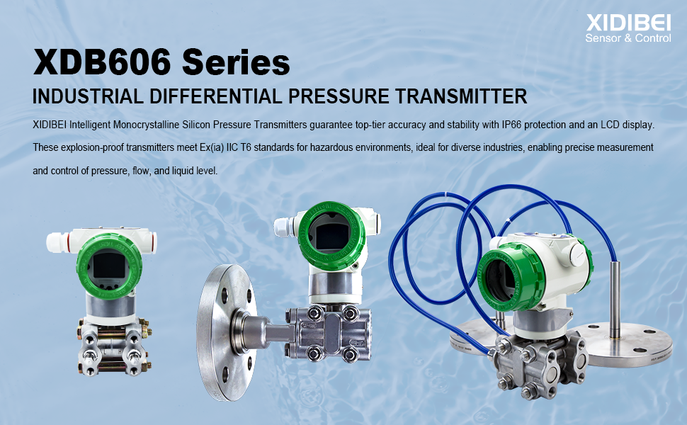
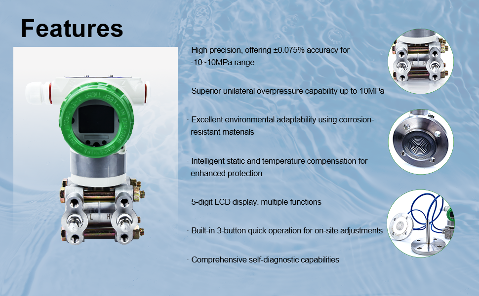
1. High Accuracy: Reference accuracy of 0.075% for standard calibration processes.
2. Exceptional Overpressure Performance: Capable of withstanding up to 16MPa of overpressure on minimal ranges.
3. Excellent Environmental Adaptability: Features intelligent static pressure and temperature compensation, minimizing measurement errors due to temperature, static pressure, and overpressure influences.
4. Superior Operability and Convenience: Equipped with a 5-digit backlit LCD display offering various functions (see selection notes), built-in three-button quick operation for local adjustments.
5. Corrosion-Resistant Materials: Available in various anti-corrosion materials.
6. Comprehensive Self-Diagnostic Functions: Ensures reliable and consistent performance.
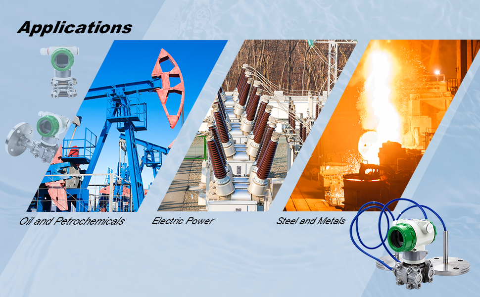
1. Oil/Petrochemical/Chemical Industry: Paired with throttling devices for precise flow measurement and control. Accurately measures pipeline and storage tank pressure and liquid level.
2. Electricity/Urban Gas/Others: Requires high stability and precision for pressure, flow, and level measurements.
3. Pulp and Paper Industry: For pressure, flow, and level measurements in environments needing resistance to chemical and corrosive liquids.
4. Steel/Non-ferrous Metals/Ceramics: Used for furnace pressure and vacuum measurements, demanding high stability and precision.
5. Mechanical Equipment/Shipbuilding: Utilized in settings where stable measurements of pressure, flow, and liquid level are critical under strictly controlled conditions.
| Pressure range | -30~30bar | Pressure Type | Gauge pressure and absolute pressure |
| Accuracy | ± 0.2%FS | Input voltage | 10.5~45V DC (intrinsic safety explosion-proof 10.5-26V DC) |
| Output signal | 4~20mA and Hart | Display | LCD |
| Power impact | ± 0.005%FS/1V | Environmental temperature | -40~85℃ |
| Housing material | Cast aluminum alloy and stainless steel (optional) |
Sensor type | Monocrystalline silicon |
| Diaphragm material | SUS316L, Hastelloy HC-276, Tantalum, gold-plated, Monel, PTFE (optional) | Receiving liquid material | Stainless steel |
| Environmental temperature impact |
± 0.095~0.11% URL/10 ℃ | Measurement medium | Gas, steam, liquid |
| Medium temperature | Depends on flange | Static pressure effect | ± 0.1%FS/10MPa |
| Stability | ± 0.1%FS/5 years | Ex-proof | Ex(ia) IIC T6 |
| Protection class | IP66 | Installation bracket | Carbon steel galvanized and stainless steel (optional) |
| Weight | ≈6.98kg | ||
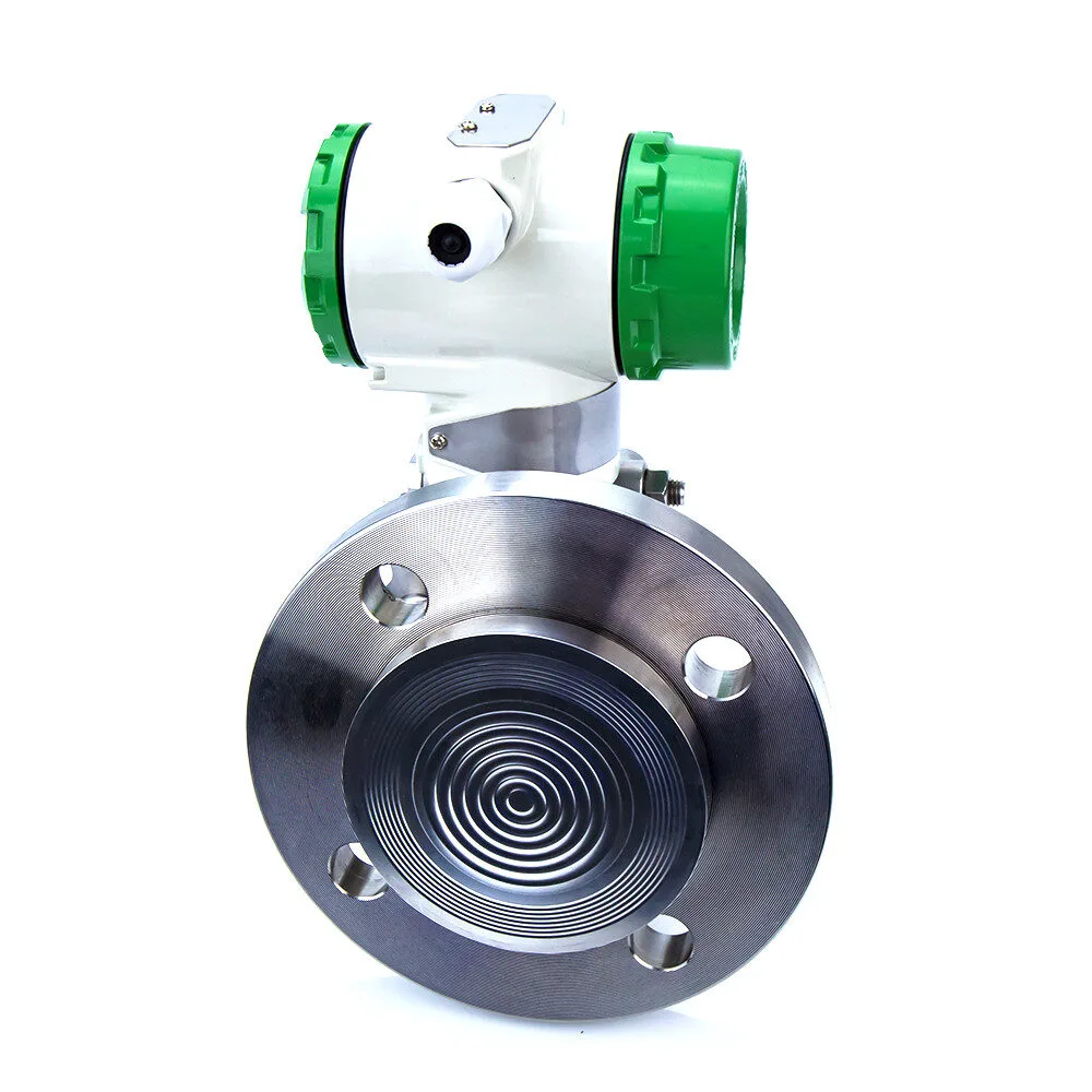
![XDB606-S1series Image[2]](https://j575.goodao.net/uploads/XDB606-S1series-Image2.jpg)
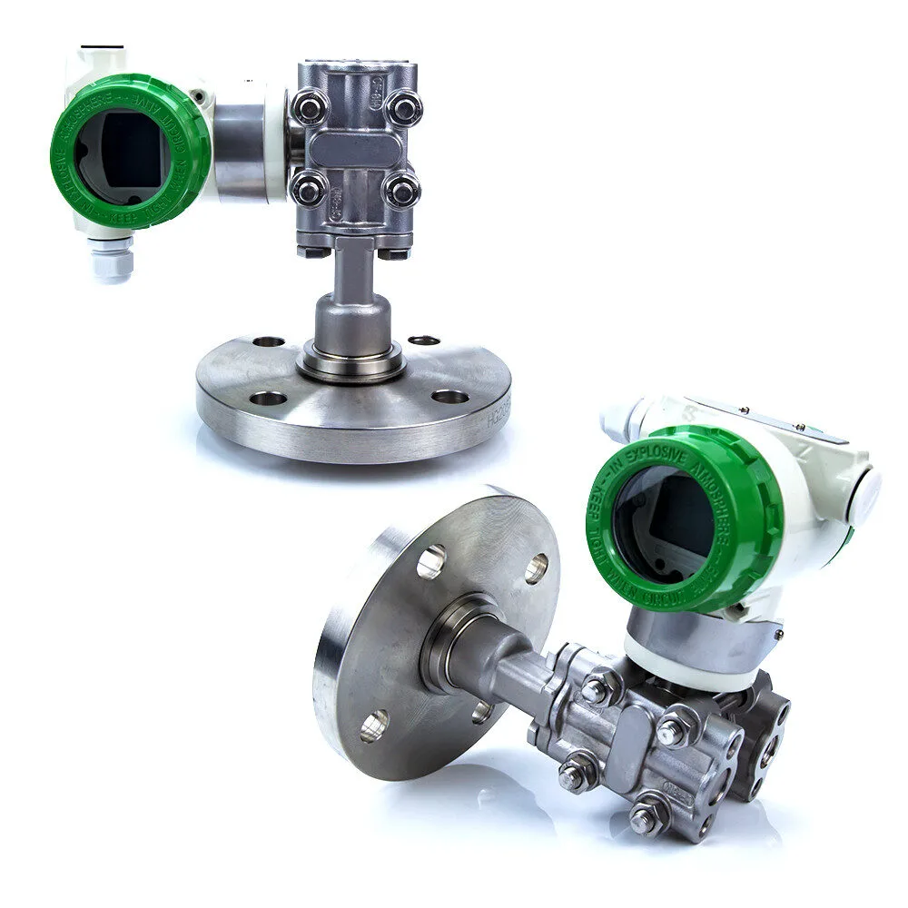
![XDB606-S1series Image[2]](https://j575.goodao.net/uploads/XDB606-S1series-Image21.jpg)
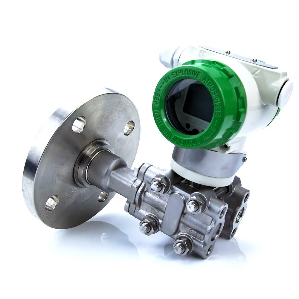
![XDB606-S1series Image[2]](https://j575.goodao.net/uploads/XDB606-S1series-Image22.jpg)
![XDB606-S1series Image[2]](https://j575.goodao.net/uploads/XDB606-S1series-Image24.jpg)
![XDB606-S1series Image[3]](https://j575.goodao.net/uploads/XDB606-S1series-Image3.jpg)
| Flat flange DN50 dimension table Unit: mm | |||||||
| Flange standard | A | B | C | D | T1 | Number of bolts(n) | Bolt hole diameter(d) |
| ANSI150 | 150 | 120.7 | 100 | 61 | 19.5 | 4 | 18 |
| ANSI300 | 165 | 127 | 100 | 61 | 22.7 | 8 | 18 |
| ANSI600 | 165 | 127 | 100 | 61 | 32.4 | 8 | 18 |
| ANSI900 | 215 | 165.1 | 100 | 61 | 45.1 | 8 | 26 |
| ANSI1500 | 215 | 165.1 | 100 | 61 | 45.1 | 8 | 26 |
| DINPN10/16 | 165 | 125 | 100 | 61 | 18 | 4 | 18 |
| DINPN25/40 | 165 | 125 | 100 | 61 | 20 | 4 | 18 |
| DIN PN 64 | 180 | 135 | 100 | 61 | 26 | 4 | 22 |
| DIN PN 100 | 195 | 145 | 100 | 61 | 28 | 4 | 26 |
| DIN PN 160 | 195 | 145 | 100 | 61 | 30 | 4 | 26 |
| Flat flange DN80 dimension table Unit: mm | |||||||
| Flange standard | A | B | C | D | T1 | Number of bolts(n) | Bolt hole diameter(d) |
| ANSI150 | 190 | 152.4 | 130 | 89 | 24.3 | 4 | 18 |
| ANSI300 | 210 | 168.3 | 130 | 89 | 29 | 8 | 22 |
| ANSI600 | 210 | 168.3 | 130 | 89 | 38.8 | 8 | 22 |
| ANSI900 | 240 | 190.5 | 130 | 89 | 45.1 | 8 | 26 |
| ANSI1500 | 265 | 203.2 | 130 | 89 | 54.7 | 8 | 33 |
| DINPN10/16 | 200 | 160 | 130 | 89 | 20 | 8 | 18 |
| DINPN25/40 | 200 | 160 | 130 | 89 | 24 | 8 | 18 |
| DIN PN 64 | 215 | 170 | 130 | 89 | 28 | 8 | 22 |
| DIN PN 100 | 230 | 180 | 130 | 89 | 32 | 8 | 26 |
| DIN PN 160 | 230 | 180 | 130 | 89 | 36 | 8 | 26 |
| Flat flange DN100 dimension table Unit: mm | |||||||
| Flange standard | A | B | C | D | T1 | Number of bolts(n) | Bolt hole diameter(d) |
| ANSI150 | 230 | 190.5 | 150 | 115 | 24.3 | 8 | 18 |
| ANSI300 | 255 | 200 | 150 | 115 | 32.2 | 8 | 22 |
| ANSI600 | 275 | 215.9 | 150 | 115 | 45.1 | 8 | 26 |
| ANSI900 | 290 | 235 | 150 | 115 | 51.5 | 8 | 33 |
| ANSI1500 | 310 | 241.3 | 150 | 115 | 61.0 | 8 | 36 |
| DINPN10/16 | 220 | 180 | 150 | 115 | 20 | 8 | 18 |
| DINPN25/40 | 235 | 190 | 150 | 115 | 24 | 8 | 22 |
| DIN PN 64 | 250 | 200 | 150 | 115 | 30 | 8 | 26 |
| DIN PN 100 | 265 | 210 | 150 | 115 | 36 | 8 | 30 |
| DIN PN 160 | 265 | 210 | 150 | 115 | 40 | 8 | 30 |

| Flat flange DN50 dimension table Unit: mm | |||||||
| Flange standard | A | B | C | D | T1 | Number of bolts(n) | Bolt hole diameter(d) |
| ANSI150 | 150 | 120.7 | 100 | 48 | 19.5 | 4 | 18 |
| ANSI300 | 165 | 127 | 100 | 48 | 22.7 | 8 | 18 |
| ANSI600 | 165 | 127 | 100 | 48 | 32.4 | 8 | 18 |
| ANSI900 | 215 | 165.1 | 100 | 48 | 45.1 | 8 | 26 |
| ANSI1500 | 215 | 165.1 | 100 | * | 45.1 | 8 | 26 |
| DINPN10/16 | 165 | 125 | 100 | 48 | 18 | 4 | 18 |
| DINPN25/40 | 165 | 125 | 100 | 48 | 20 | 4 | 18 |
| DIN PN 64 | 180 | 135 | 100 | 48 | 26 | 4 | 22 |
| DIN PN 100 | 195 | 145 | 100 | 48 | 28 | 4 | 26 |
| DIN PN 160 | 195 | 145 | 100 | 48 | 30 | 4 | 26 |
| Flat flange DN80 dimension table Unit: mm | |||||||
| Flange standard | A | B | C | D | T1 | Number of bolts(n) | Bolt hole diameter(d) |
| ANSI150 | 190 | 152.4 | 130 | 71 | 24.3 | 4 | 18 |
| ANSI300 | 210 | 168.3 | 130 | 71 | 29 | 8 | 22 |
| ANSI600 | 210 | 168.3 | 130 | 71 | 38.8 | 8 | 22 |
| ANSI900 | 240 | 190.5 | 130 | 71 | 45.1 | 8 | 26 |
| ANSI1500 | 265 | 203.2 | 130 | * | 54.7 | 8 | 33 |
| DINPN10/16 | 200 | 160 | 130 | 71 | 20 | 8 | 18 |
| DINPN25/40 | 200 | 160 | 130 | 71 | 24 | 8 | 18 |
| DIN PN 64 | 215 | 170 | 130 | 71 | 28 | 8 | 22 |
| DIN PN 100 | 230 | 180 | 130 | 71 | 32 | 8 | 26 |
| DIN PN 160 | 230 | 180 | 130 | 71 | 36 | 8 | 26 |
| Flat flange DN100 dimension table Unit: mm | |||||||
| Flange standard | A | B | C | D | T1 | Number of bolts(n) | Bolt hole diameter(d) |
| ANSI150 | 230 | 190.5 | 150 | 96 | 24.3 | 8 | 18 |
| ANSI300 | 255 | 200 | 150 | 96 | 32.2 | 8 | 22 |
| ANSI600 | 275 | 215.9 | 150 | 96 | 45.1 | 8 | 26 |
| ANSI900 | 290 | 235 | 150 | 96 | 51.5 | 8 | 33 |
| ANSI1500 | 310 | 241.3 | 150 | * | 61.0 | 8 | 36 |
| DINPN10/16 | 220 | 180 | 150 | 96 | 20 | 8 | 18 |
| DINPN25/40 | 235 | 190 | 150 | 96 | 24 | 8 | 22 |
| DIN PN 64 | 250 | 200 | 150 | 96 | 30 | 8 | 26 |
| DIN PN 100 | 265 | 210 | 150 | 96 | 36 | 8 | 30 |
| DIN PN 160 | 265 | 210 | 150 | 96 | 40 | 8 | 30 |
E.g. XDB606 – S1 – H – R1 – W1 – SS – C1 -G1 -D1 – A – X1 – DY – M20 – M – H – Q
| Model/Item | Specification code | Description |
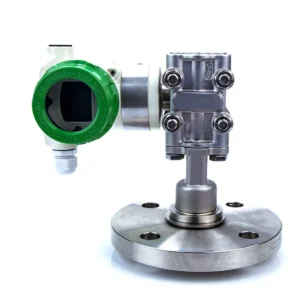
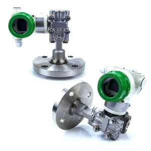
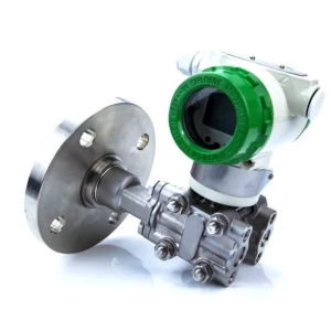
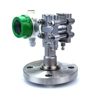
| XDB606 | S1 | Single Flange Level Transmitter |
| Output signal | H | 4-20mA, Hart, 2-wire |
| Measuring range | R1 | 1~6kPa Range: -6~6kPa Overload limit: 2MPa |
| R2 | 4~40kPa Range: -40~40kPa Overload limit: 7MPa | |
| R3 | 10~100KPa, Range: -100~100kPa Overload limit: 7MPa | |
| R4 | 40~400KPa, Range: -100~400kPa Overload limit: 7MPa | |
| R5 | 0.3-3MPa, Range: -0.1-3MPa Overload limit: 7MPa | |
| Housing material | W1 | Cast aluminum alloy |
| W2 | Stainless steel | |
| Receiving liquid material | SS | Diaphragm: SUS316L, Other receiving liquid materials: stainless steel |
| HC | Diaphragm: Hastelloy HC-276 Other liquid contact materials: stainless steel | |
| TA | Diaphragm: Tantalum Other Liquid Contact Materials: Stainless Steel | |
| GD | Diaphragm: gold-plated, other liquid contact materials: stainless steel | |
| MD | Diaphragm: Monel Other liquid contact materials: stainless steel | |
| PTFE | Diaphragm: PTFE coating Other liquid contact materials: stainless steel | |
| Low Pressure Side Process Connection |
C1 | 1/4 NPT female |
| C2 | 1/2 NPT female | |
| High-Pressure Side Flange
Specification
|
G1 | GB/T9119-2010 (National Standard): 1.6MPa |
| G2 | HG20592 (Chemical Industry Standard): 1.6MPa | |
| G3 | DIN (German Standard): 1.6MPa | |
| G4 | ANSI (American Standard): 1.6MPa | |
| GX | Customized | |
| High Pressure Side Flange Size |
D1 | DN25 |
| D2 | DN50 | |
| D3 | DN80 | |
| D4 | DN100 | |
| D5 | Customized | |
| Flange Material | A | 304 |
| B | 316 | |
| C | Customized | |
| Diaphragm Protrusion Length | X1 | ***mm |
| Capillary Length | DY | ***mm |
| Electrical connection | M20 | M20 * 1.5 female with a blind plug and an electrical connector |
| N12 | 1/2NPT female with a blind plug and an electrical connector | |
| Display | M | LCD display with buttons |
| L | LCD display without buttons | |
| N | NONE | |
| 2-inch pipe installation
bracket |
H | Bracket |
| N | NONE | |
| Bracket material | Q | Carbon steel galvanized |
| S | Stainless steel |